Reading
Configuration
| Display |
Action |
Response |
|
|
Press
MENU
Press ENTER
|
1) Press
MENU, if necessary,
until "Reading
Configuration"
prompt appears.
2) Display
advances to "dEc.Pt"
(decimal Point). |
|
|
Press
ENTER
Press MAX
Press ENTER |
DECIMAL
POINT SUBMENU:
3) Display
flashes previous
selection for decimal
location.
4) Scroll
though the available
selections and
choose decimal
location: FFFF.
or FFF.F (also
F.FFF and FF.FF
ù if "Process"
type was selected
in the "Input Type"
menu).
5) Display
flashes "strd"
message and advances
to "Temperature
Unit".
Note: Decimal
point for Process
input type is passive. |
|
|
Press
ENTER
Press MAX
Press ENTER |
TEMPERATURE
UNIT SUBMENU:
6) Display
flashes previous
Temperature Unit
selection.
7) Scroll
though the available
selections to
the temperature
unit of your
choice: ░F or
░C.
8) Display
flashes "strd"
message and advances
to "Filter Constant".
|
|
|
Press
ENTER
Press MAX |
FILTER
CONSTANT SUBMENU:
9) Display
flashes previous
selection for
filter constant.
10) Scroll
though the available
selections: 0001,
0002, 0004, 0008,
0016, 0032, 0064,
0128. - Default
is 0004 |
|
|
Press
ENTER |
11)
Display flashes
"stored" message
only if change
was made.
Note:
For PID control
select filter
value 0001-0004.
A filter value
of 2 is approximately
equal to 1 sec.
RC low pass time
constant.
IF Process
was selected
in the "Input
Type" menu the
display will
advance to "Input
SC & OFF", otherwise
the display advances
to the "Alarm
1"menu. 0001 |
Note:
The Filter Constant
submenu allows the
user to specify the
number of readings
stored in the digital
averaging filter.
Reading
Configuration (If Process
was selected)
| Display |
Action |
Response |
|
|
Press
ENTER
Press MAX & MIN
Press ENTER
Press MAX & MIN
Press ENTER
|
INPUT
SCALE & OFFSET
SUBMENU:
12) Press
enter at the
"Inpt SC.0F"
prompt. Display
flashes 1st digit
in submenu "In
1"
13) Use
MAX and MIN buttons
to enter "In
1" value. The
"In 1" value
= min. input
value *the natural
gain. Example:
4(mA) x 500 =
2000
14) Display
advances to "RD
1" submenu.
15) Use
MAX and MIN buttons
to enter "RD
1" value. This
value responds
to In 1 in terms
of some meaningful
engineering units
16) Display
advances to "In
2" submenu. The
"In 2" value
= max. input
value *the natural
gain. Example:
20(mA) x 500
= 10000 (9999) |
|
|
Press
MAX & MIN
Press ENTER
Press MAX & MIN
Press ENTER |
17)
Use MAX and MIN
buttons to enter
"In 2" value.
18) Display
advances to "
RD 2 " submenu.
19) Use
MAX and MIN buttons
to enter " RD
2 " value.
20) Display
flashes "stored"
message and advances
to "AlAr 1" menu.
Note: This
submenu allows
the user to scale
the meter when
in process mode
and the above
display value
is an example
for 4-20mA input
(4 to 20mA =
0000 to 0100%).
RD 2 0100. 9999. |
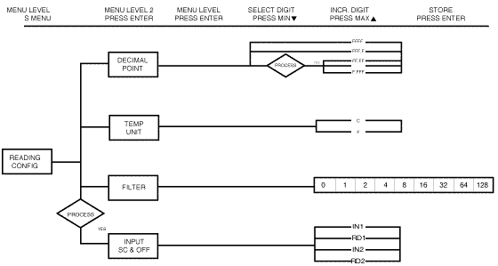
Figure 3.3
Flowchart
for Reading Configuration
Alarm
1
| Display
|
Action |
Response |
|
|
Press
MENU
Press ENTER |
1)
Press MENU, if
necessary, until
"Alar 1" prompt
appears.
2) Display
advances to "Alar.1
enbl" or "dsbl"
submenu. |

|
Press MAX
Press ENTER
|
ALARM
1 ENABLE/DISABLE
SUBMENU:
3) Display
flashes previous
selection. Press
MAX until "Enbl"
displays to use
Alarm 1.
4) Display
flashes "strd"
message only
if it was changed,
otherwise press
MENU to advances
to "Control Type"
submenu. |
|
|
Press MAX
Press ENTER |
ALARM
TYPE SUBMENU:
5) Display
flashes previous
selection. Press
MAX to "AbSo"
or "dEu." Press
ENTER
6) Display
flashes "strd"
message only
if it was changed,
otherwise press
MENU to advances
to "Alarm 1 Latch"
submenu. |
Note:
Absolute mode allows
Alarm 1 to function
independently from
Set Point 1. If the
process being monitored
does not change often,
then "absolute" mode
is recommended.
Deviation mode allows
changes to setpoint
1 to be made automatically
to Alarm 1. Deviation
mode is typically the
ideal mode if the process
temperature changes
often. In deviation
mode, set Alarm 1 a
certain number of degrees
or counts away from
Set Point 1 ù this
relation remains fixed
even if Set Point 1
is changed.
|
|
Press
MAX
Press ENTER |
ALARM
LATCHED OR UNLATCHED
SUBMENU:
7) Display
flashes previous
selection. Press
MAX to Latched
or Unlatched.
8) Display
flashes "strd"
message and advances
to "Contact Closure"
submenu |

|
Press MAX
Press ENTER
|
CONTACT
CLOSURE SUBMENU:
9) Display
flashes previous
selection. Press
MAX to Normally
Closed (n.c.)
or Normally
Open (n.o.).
10) Display
flashes "strd"
message only
if it was changed,
otherwise press
MENU to advances
to "A.P.on" Enable/Disable. |
|
|
Press MAX
Press ENTER
|
ALARM
1 SETUP SUBMENU:
13) Display
flashes previous
selection. Press
MAX to scroll
through the available
selections: Above,
Below, HI/Low
and Band
(Band is active
if "Deviation"
was selected).
14) Display
flashes "strd"
message only
if it was changed,
otherwise press
MENU to advances
to "Alarm 1 Low
Value" submenu. |
Above:
Alarm 1 condition triggered
when the process variable
is greater than the
Alarm Hi Value. (Lo
value ignored)
Below: Alarm
1 condition triggered
when the process variable
is less than the Alarm
Low Value. (Hi value
ignored)
Hi/Low: Alarm
1 condition triggered
when the process variable
is less than the Alarm
Low Value or above
the Hi Value
Band:
Alarm 1 condition triggered
when the process variable
is above or below the
"band" set around Set
Point 1. Band equals
Hi Value (Lo Value
ignored). A "band"
is set around the Hi
Value by the controller
only in the "deviation"
mode.
|
|
Press
MAX
Press ENTER |
ALARMS
ENABLE/DISABLE
AT POWER ON:
11) Display
flashes previous
selection. Press
MAX to enable
or disable.
12) Display
flashes "stored"
message only
if it was changed,
otherwise press
MENU to advances
to the "Alarm
Setup" submenu. |
| Note:
If the alarm
is enabled at
Power On, the
alarm will be
active right
after reset.
If the alarm
is disabled at
Power On, the
alarm will become
enabled when
the process value
enters the non
alarm area. The
alarm is not
active while
the process value
is approaching
set point 1. |

|
Press MAX &
MIN
Press ENTER
|
ALARM
1 LOW VALUE SUBMENU:
15) Display
flashes 1st digit
of previous value.
Use MAX and MIN
to enter new
value.
16) Display
flashes "strd"
message and advances
to "Alarm 1 HI
Value" submenu. |
|
|
Press MAX &
MIN
Press ENTER
|
ALARM
1 HI VALUE SUBMENU:
17) Display
flashes 1st digit
of previous value.
Use MAX and MIN
to enter new
value.
18) Display
flashes "strd"
message only
if it was changed,
otherwise press
MENU to advances
to "Alarm 2"
submenu. |
Note:
Latched
mode: Relay remains
"latched" until reset.
To reset already latched
alarm, select Alarm
Latch and press Max
twice (i.e. Unlatch
and then back to Latch.)
Unlatched mode:
Relay remains latched
only as long as the
alarm condition is
true.
Normally Closed:
"Fail Safe" mode,
relay is energized
under "normal" conditions
and becomes de-energized
during alarm or power
failure.
Normally Open:
If this feature is
selected, then the
relay is "energized"
only when an alarm
condition occurs.
Alarm
2
| Display
|
Action |
Response |
|
|
Press
MENU
Press ENTER |
1)
Press MENU, if
necessary, until
"Alar 2" display
appears.
2) Display
advances to "Alarm
2 Enable/Disable"
submenu. |

|
Press MENU
|
IF
ALARM 2 IS NOT
INSTALLED, THE
CONTROLLER WILL
SHOW "NOT INSTALLED"
Press MENU, if
you receive the
"not installed"
message and advance
to the "Loop
Break" menu.
|
|
|
Press MAX
Press ENTER
|
Alarm
2 enable/disable
Submenu:
3) Display
flashes previous
selection. Press
MAX until "Enbl"
displays to use
Alarm 2.
4) Display
flashes "strd"
message only
if it was changed,
otherwise press
MENU to advances
to "Control Type"
submenu. |
The
remaining Alarm 2 is
identical to Alarm
1 i.e. previous two
pages.
Modifying
Alarm Settings will
not reset the Controller
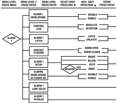

Figure
3.4 Flowchart
for Alarm 1 and Alarm
2
Loop
Break Alarm
| Display
|
Action |
Response |
|
|
Press
MENU
Press ENTER |
1)
Press MENU, if
necessary, until
the "Loop Break"
prompt appears.
2) Display
advances to "Loop
Break Enable/Disable"
submenu. |
|
|
Press ENTER
Press MAX
Press ENTER
|
LOOP
BREAK ENABLE/DISABLE
SUBMENU:
3) Display
flashes "enbl"
or "dsbl".
4) Scroll
through the available
selections: Enable
(enbl) or Disable
(dSbl).
5) Display
flashes "strd"
message and advances
to "Loop Value"
menu. |
Note:
Loop
Break is an additional
safety feature intended
to monitor the rate
of change of the process
value, while approaching
the SPI. It is strictly
intended as an additional
warning system, therefore
itÆs use is entirely
optional. An active
Loop Break will cause
the Set Point digits
to blink in a rotating
pattern. If the process
value reaches the set
point the blinking
will stop and Loop
brA1 is completed successfully,
otherwise Loop brA1
will flash and will
activate Alr1.
|
|
Press
ENTER
Press MAX & MIN
Press ENTER |
LOOP
BREAK ALARM VALUE
SUBMENU:
6)
Display flashes
1st digit of
previous loop
value.
7) Press
MAX and MIN buttons
to enter a new
"loop value".
8) Display
flashes "strd"
message and advances
to "CJ Temperature
Adjust" menu. |
|
|
Press ENTER
Press MAX & MIN
Press ENTER
|
TEMPERATURE
ADJUST SUBMENU:
9) Display
flashes 1st digit
of previous temperature
adjust value.
10) Press
MAX and MIN buttons
to enter a new
"temperature
adjust" value
11) Display
flashes "strd"
message and advances
to "ID Option"
submenu. |
Note:
Loop Break Alarm Value
allows the user to
determine the time
interval in MM:SS (from
zero to 99 minutes
and 59 seconds) that
the process value changes
10 counts or if the
input type is either
RTD or Thermocouple,
the value would be
░4 Fahrenheit or 2░
Celsius. At the specified
time interval, if the
process value change
is less than the stated
rate flashing, " L.B.AL
" will be displayed,
the output "1" will
be de-energized, and
Alarm 1 energized.
Loop break alarm will
be disabled when the
process value (PV)
enters the control
band.
Tip: Display Offset
Adjust allows the
user to fine tune a
minor error of the
transducer, however
some applications may
require a large offset
adjust. (Displayed
Process Value = Measured
Process Value ▒ t.A.dJ).
t.A.dJ is adjustable
between -1999 to 9999.
|
|
Press MAX
Press ENTER |
ID
CODE OPTION SUBMENU
12) Display
flashes current
status of ID
Option, enabled
or disabled.
13) Press
MAX button to
select between
Enable and Disable
14) Display
flashes "strd"
and advances
to "Output
1." |
NOTE:
With ID Code Option
disabled, the ID Number
submenu is hidden.
Refer to the appropriate
Set Points section
for setting differences.
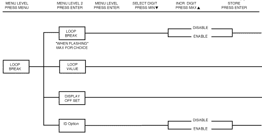
Figure 3.5
Flowchart
for Loop Break
|
 TOC
TOC  Back
Back  Next
Next


